
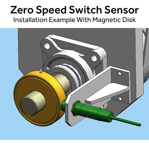


The ZS09R is designed for straightforward installation on rotating equipment where dependable speed detection is needed. Point the sensor at a suitable rotating target such as a gear tooth, bolt head, key stock, or magnetic target. Then connect the relay contacts to the equipment control circuit.
Its adjustable set point allows the ZS09R to respond to the speed conditions required by the application. The sensor can monitor rotating shafts on conveyors, bucket elevators, augers, exhaust fans, turbines, and other industrial machinery. Isolated relay contacts make the ZS09R a practical choice for new installations, retrofit projects, and replacement of obsolete or unreliable zero speed switches.
Product Detail
The ZS09R monitors the rotation of a machine shaft by sensing each passing target. The sensor can detect high-iron targets such as gear teeth, bolt heads, and key stock, as well as Phares magnetic targets. Unlike a conventional proximity switch that simply detects the presence of a target, the ZS09R evaluates the rate at which targets pass the sensor to determine shaft speed.
The relay set point can be adjusted to the speed required by the application. As the shaft reaches the selected speed, the relay changes state. If the shaft slows below the set point or stops, the relay returns to its normal state. This makes the ZS09R useful for detecting conditions such as conveyor slowdown, belt slippage, loss of rotation, or other changes in machine speed.
The ZS09R provides isolated relay contacts for connecting the speed signal to a PLC, VFD, DCS, or other low-power control circuit. Its compact threaded housing allows the sensor to be installed directly at the point of measurement, eliminating the need to run a separate speed sensor back to a control panel.
For applications requiring higher-amperage relay switching, the Phares ZS09P provides up to 5 Amps of switching capacity. The ZS09R is the appropriate choice when the speed signal will be used as a control or logic input.
Features
- Sensor and relay combined in a single unit
- Isolated Form ‘C’ relay contacts switches 1 Amp
- Designed for switching logic inputs (PLC, VFD, DCS, etc.)
- No programming or external control required
- Detects stopped or slow motion promptly
- Easy to install and adjust
- Suitable for outdoor use and in wash down areas (IP67)
- Senses magnetic and high iron content targets (gear tooth, key stock, bolt head, etc.)
- LED indicators for instant visual confirmation
- Precision trim pot for accurate relay set point adjustment (IP67)
- Detect speeds as slow as 0.02 RPM
- Detect speeds as high as 25,000 RPM
Benefits
- Provides a simple speed-monitoring signal to existing control systems
- Easy replacement for obsolete or unreliable zero-speed switches
- Connects directly to PLC, VFD, and DCS logic circuits
- Helps detect equipment slowdowns before they lead to larger failures
- Mounts directly at the point of measurement
- Eliminates the need for a separate control box
- Isolated relay contacts simplify integration with new or existing systems
- Suitable for conveyors and a wide range of rotating industrial equipment
Specifications
| Operating Voltages | 5-24 VDC or 120 VAC |
|---|---|
| Operating Temperature | -40°F to 140°F |
| Operating Frequency | Hall Effect and Inductive (Gear Tooth): 0.02Hz-10kHz Hall Effect Only: 0.02Hz – 25kHz |
| Relay Contact Ratings |
250 VAC, 220 VDC Maximum, 1 Amp Vibration resistance: Shock resistance: |
| Relay Set-Point Adjustment Range | Standard: 1-100 RPM, 1 Pulse Per Revolution Custom parameters are available. |
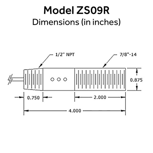
| Housing Material | Aluminum |
| Fuse | Internal 1/2 Amp non-replaceable fuse |
| Cable | 4 ft., 6 Conductor, 22 AWG, Unshielded |
| Sensing Distance to Target (Gap) | 1/16″ to 5/16″ using Ferrous Target (Gear Tooth Wheel, Bolt Head, Key Stock, etc.) 1/2″ to 5/8″ using Phares Magnetic Disk 1″ using Phares Magnet, Part No. SM-100 |
| Minimum Gear Tooth Target Sizes | 1/8″ gear tooth length, width, depth and gap. |
| Gear Tooth Target Material | High ferrous (iron) content. |
Wiring & Installation
Installation is simple:
- Mount the ZS09R sensor and aim at a rotating target such as a bolt head, key stock, flat washer, or magnet. When using a ferrous metal target, ensure it has a high iron content. Stainless steel and iron alloys are not suitable and will not trigger the sensor reliably.
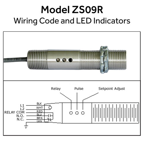
- Connect the relay output to the appropriate control circuit. The isolated N.O. or N.C. relay contacts can be connected to a PLC, VFD, DCS, or other low-power control input.
- Set the operating speed using the adjustment potentiometer on the sensor. Adjust the set point to the speed at which you want the relay to change state.
The built-in LED indicators provide a convenient visual indication of sensor and relay operation.
Frequently Asked Questions
Q: What is the difference between the ZS09R and ZS09P?
A: The main difference is the relay output. The ZS09R uses a 1 Amp reed relay and is intended primarily for switching low-power logic inputs such as PLCs, VFDs, DCS systems, and other control inputs. The ZS09P uses a 5 Amp relay for higher-current control circuits.
Q: Can the ZS09R zero speed switch connect to a PLC?
A: Yes. The ZS09R provides isolated relay contacts that can be connected to a PLC input or other low-power control circuit. No separate zero speed controller is required.
Q: What type of targets can the ZS09R detect?
A: The ZS09R can detect high-iron targets such as gear teeth, bolt heads, and key stock. It can also be used with Phares magnetic disks and magnets. Ferrous targets must have a high iron content; stainless steel and some iron alloys will not trigger the sensor reliably.
Q: What does the ZS09R do when machine speed falls below the set point?
A: When the monitored shaft speed falls below the set point or stops, the relay changes back to its normal state. This provides the control system with a signal that the equipment is no longer operating at the required speed.
Q: Can the ZS09R be used to detect an underspeed condition before the machine stops?
A: Yes. The adjustable relay set point allows the ZS09R to respond when shaft speed falls to a predetermined RPM. This makes it useful for detecting conditions such as conveyor slowdown, belt slippage, or other developing equipment problems.
Q: How far should the ZS09R be from the rotating target?
A: For ferrous targets, the recommended sensing gap is approximately 1/16 inch to 5/16 inch. When using a Phares magnetic disk, the recommended distance is approximately 1/2 inch to 5/8 inch. A Phares SM-100 magnet can be sensed at approximately 1 inch.
Q: Does the ZS09R require a separate controller?
A: No. The sensor and zero speed switch circuitry are contained in the ZS09R. The relay output can be wired directly into the appropriate control or logic circuit.
Q: Where is the ZS09R commonly used?
A: Typical applications include conveyors, bucket elevators, augers, exhaust fans, turbines, and other rotating machinery where a PLC or other control system needs a reliable indication of shaft speed or loss of rotation.
More Solutions…
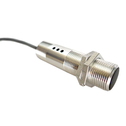
ZS09P Zero Speed Switch Sensor
The ZS09P is a compact, self-contained zero speed switch for applications requiring a higher-power relay output. It switches loads up to 5 amps, making it a good choice for directly controlling equipment or control circuits without a separate control module.

ZS10 Zero Speed Switch Module
The ZS10 is a DIN rail-mounted zero speed switch module that works with your choice of industrial sensor. The sensor must provide a digital square wave signal. This flexible configuration keeps the sensor at the machine while the control module can be mounted safely inside a control panel. The ZS10 is well suited for industrial speed monitoring applications where a separate sensor and control module are preferred.
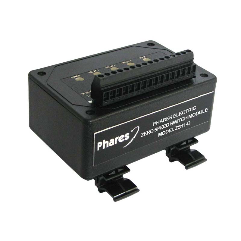
ZS11 Zero Speed Switch Module
The ZS11 is designed for applications requiring multiple speed setpoints from one sensing location. Its three independent relay outputs allow different speed conditions to be monitored without using multiple PLC inputs or separate zero speed modules.
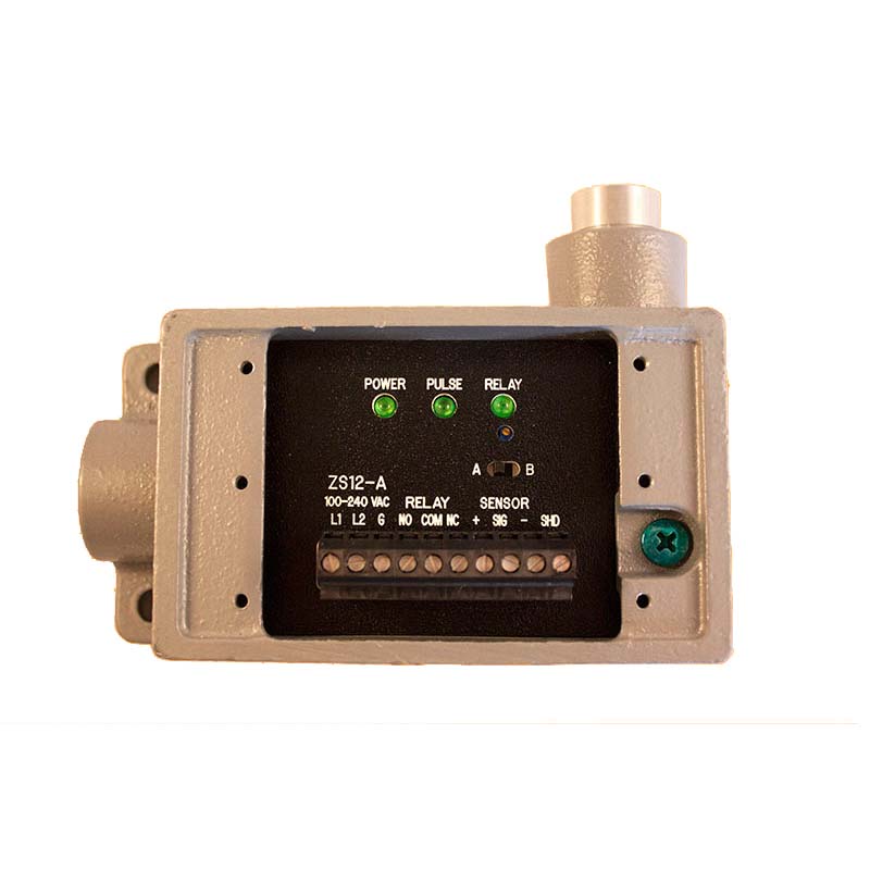
ZS12 Zero Speed Switch
The ZS12 combines speed sensing and relay control in a rugged cast-aluminum enclosure designed for demanding industrial environments. Its replaceable sensor and point-of-measure installation make it a strong choice where durability, serviceability, and washdown resistance are important.